After months of research and design the build of the prototype took around 2.5 months, working Monday – Friday, 9-5, in a shared workshop. This set of photo’s documents a small amount of the design work and the entire build process to completion.
Click on any image to begin full screen view.
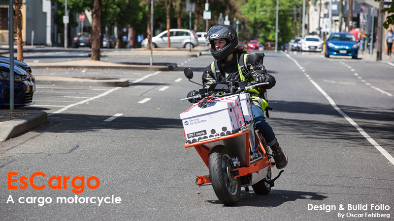
Design and Build Folio
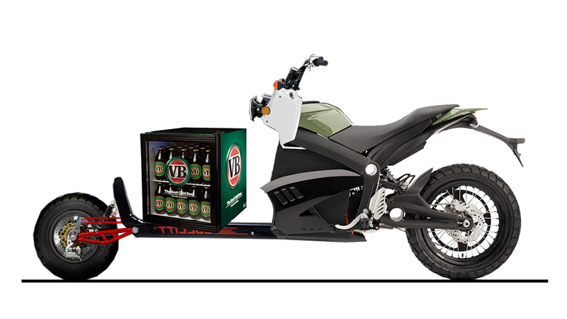
Hack photoshop: The first illustration of an electric cargo motorcycle. Sometimes a rough visualization is needed to explain to people what you’re on about! The VB fridge was added for Aussie impact.
Mood Board: Keywords and design themes that were to be incorporated within the project.
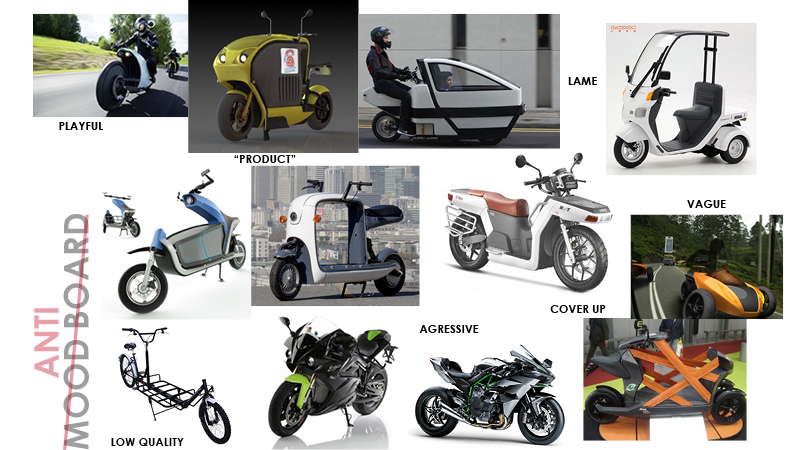
Anti Mood Board: Concepts that were NOT to be included in the project.
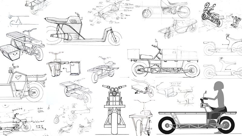
Sketching: There was a huge amount of sketching. Mostly chicken scratch engineering details. Only included a tiny amount here to give you an idea.
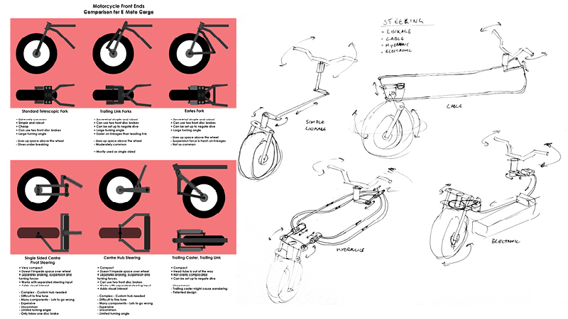
The front end: One of the biggest and toughest decisions was the front end and steering method used. In the end a custom “funny front end” was designed (not shown here) and cable steering was chosen.
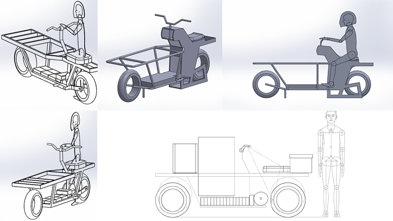
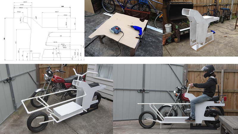
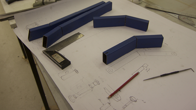
1:1 model plans and packaging: To understand what the scale and proportions were in real life and what kind of cargo and components could fit where.
1:1 white model build: Now it’s possible to see the scale of the bike and compare with a standard motorcycle reference.
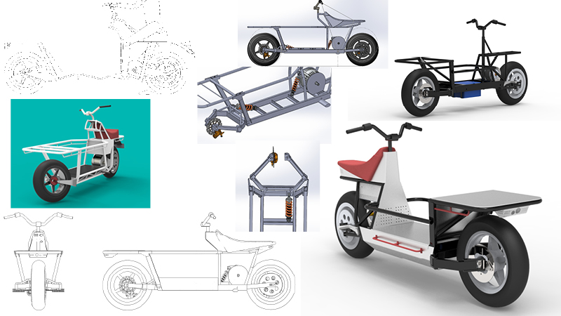
CAD development (early): The CAD model went through many iterations and developments. Started with a long trellis frame and slowly reduced and simplified it.
CAD Headspin: At this point the complexity of the project was hugely apparent and there was doubt whether making a working prototype was even possible in the time frame. Constantly working in CAD doesn’t help; you get stuck in ruts easily and begin to overthink every little detail.
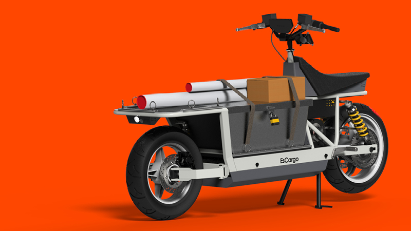
CAD development (for manufacture): The design that was landed on, ready to start manufacturing.
CAD Development (final): The CAD model continued to develop throughout the build process and ended up as shown here.
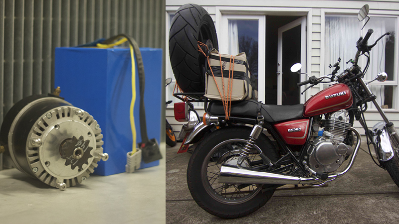
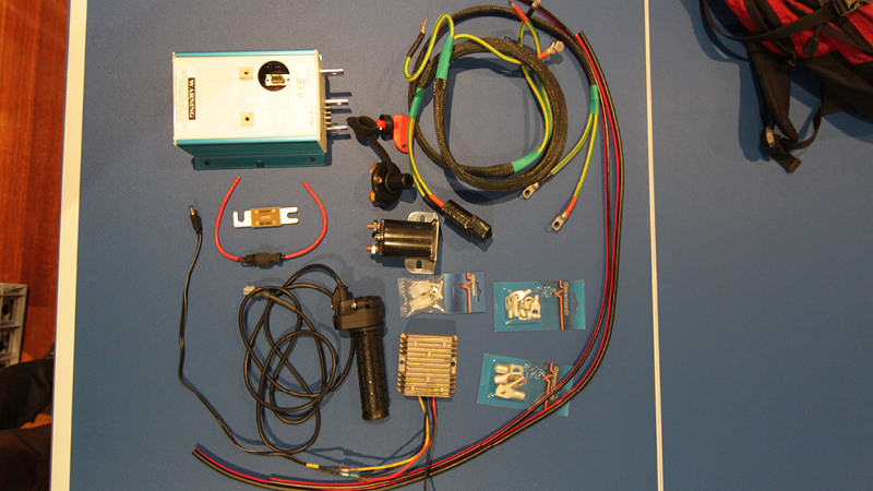
Components sourced: Power train components were sourced from a previous Industrial Design student. Carrying all that heavy gear on the back of a GN250 was “interesting”… It also confirmed the design decision of going with the “dutch cargo bike” design for EsCargo – having a large mass loaded high and at the rear is not ideal.
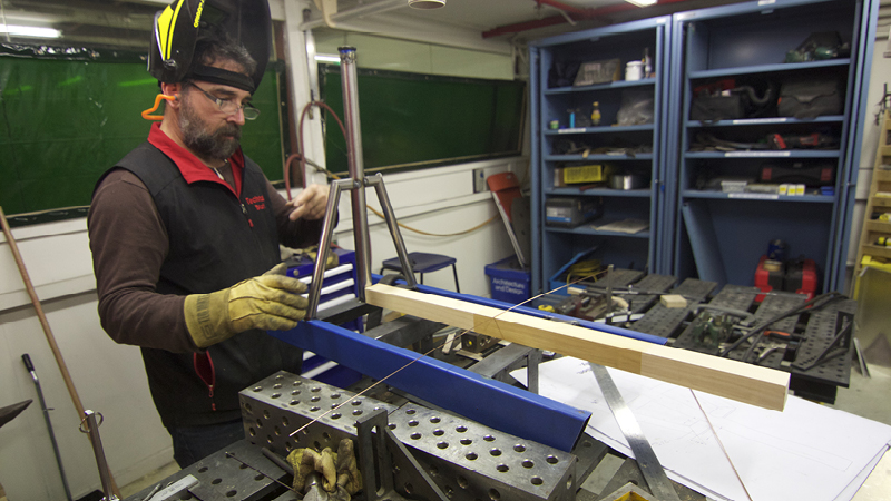
Front end geometery: Many more iterations on designing the front end. The concept was borrowed from some DIY cargo bicycles seen online. This concept was redesign to maximise it’s turning angle, but minimise the overall width. Wooden prototypes were made to make 100% sure the right path was being taken. This front end was a huge gamble.
Handmade: A lot of the fabrication was done by hand. It might seem backwards considering the amount of high tech gear the University workshop has, but in the end it was faster and much more flexible to work by hand.
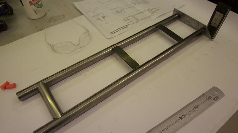
1:1 construction drawings: All the frame components were printed at 1:1 so it was possible to work straight from them. Here the angle cuts have been made into the “front rack supports” and the “front claw arms.”
Tail piece.
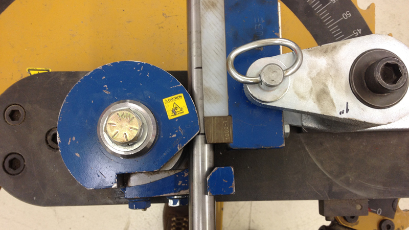
Pipe bending was avoided in some areas due to time constraints/ease, but there were still a few bends necessary throughout the design.
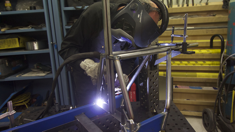
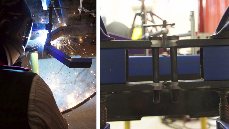
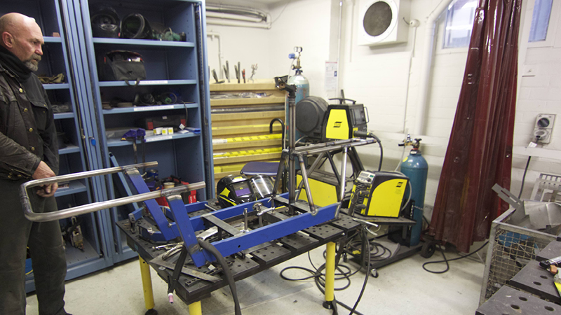
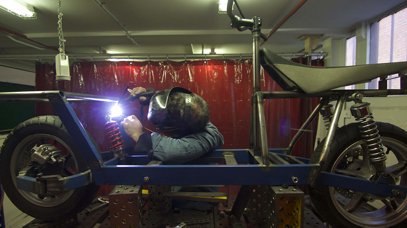
Roni welding: Battery box has been welded to the frame rails and the back end of the frame is beginning to be tacked. Roni (pictured) was one of two welders heavily relied on.
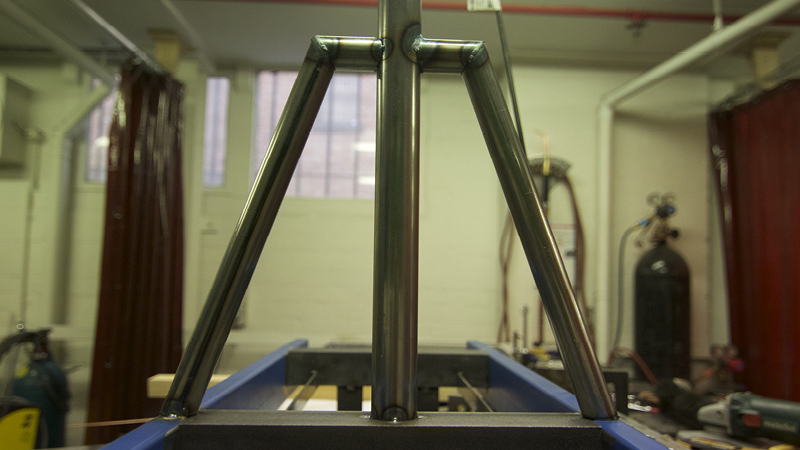
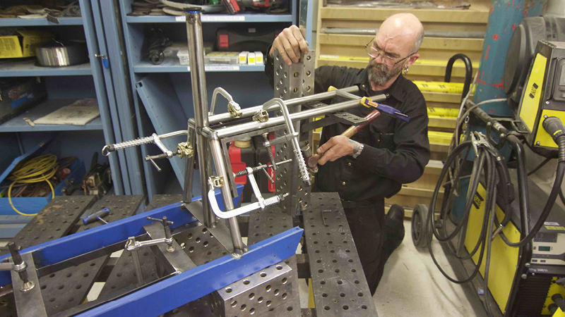
Steering column tube and supports.
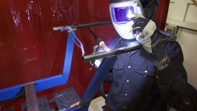
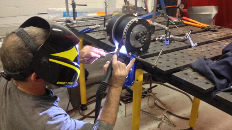
Craig Longhurst welding: Craig was a legend during this project and it’s unlikely that it would have come together without him. He’s been in the custom motorcycle business (at Mischief Makers) for many years and is an excellent welder.
Rear claw arm welding.
Rear frame welding.
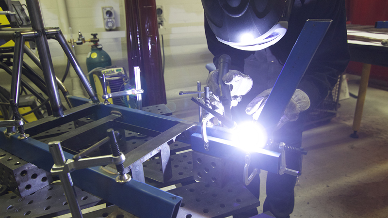
Front rack support welding.
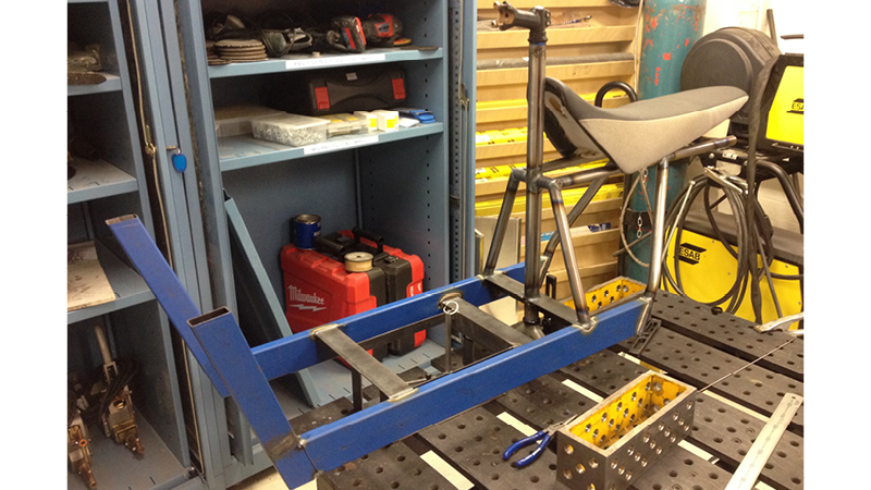
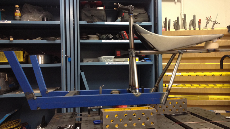
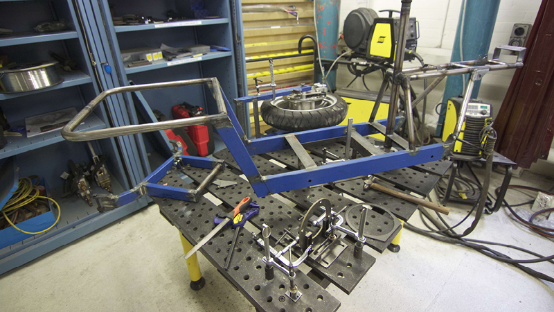
Frame early days.
Frame early days 2.
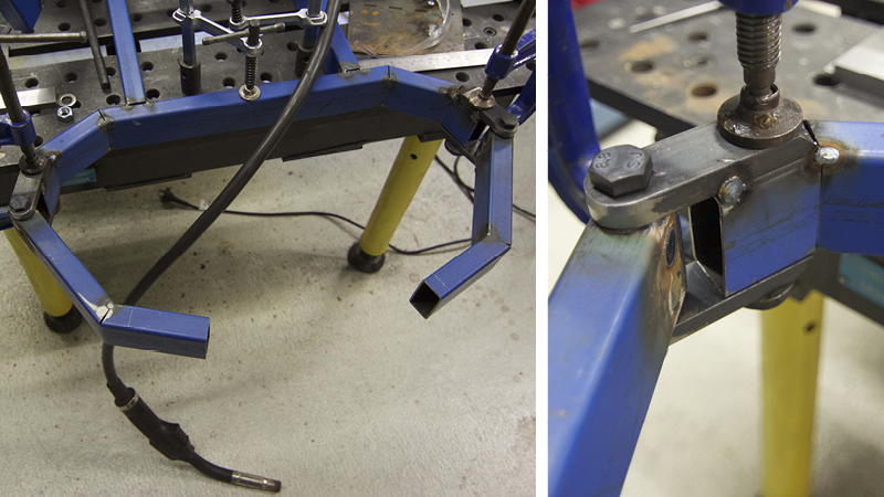
Front end check: Getting everything lined up and clamped was extremely difficult.
Front end before welding.
Front end tacked.
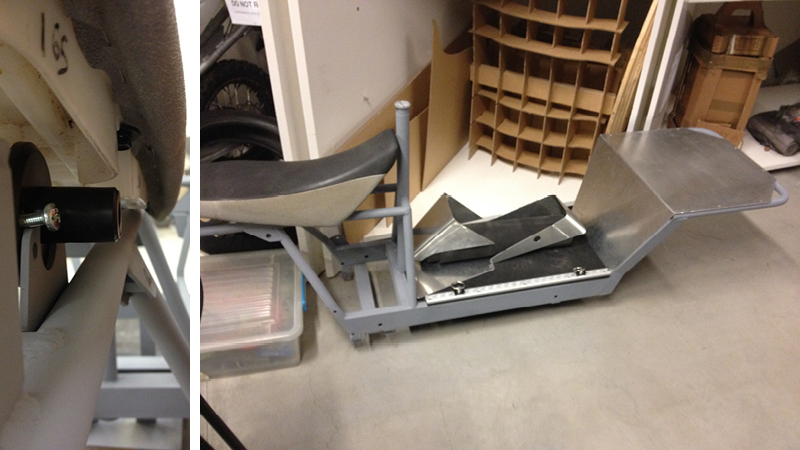
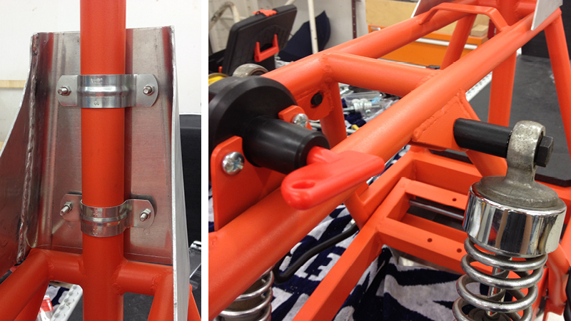
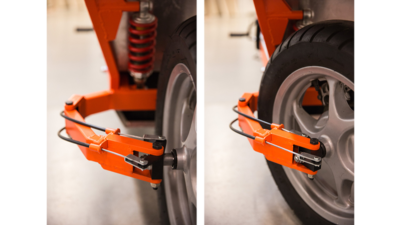
Front end welded: Left photo shows the most critical aspect. Both “claws” needed to line up exactly, otherwise the front wheel would never align and the steering would be tight. All the pivoting members in the front end are simply grease joints. A bolt runs through a solid steel section and grease provides the lubrication
Welding the front rack
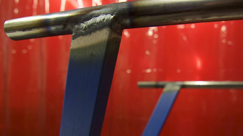
Nice welds.
Frame is getting there.
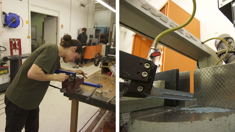
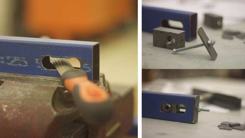
Hand filing the rear axel slots (left). Got a lot of use out of the horizontal bandsaw (right)
Rear axel adjusters. Something to redesign and remake. These do the job, but can be much better.
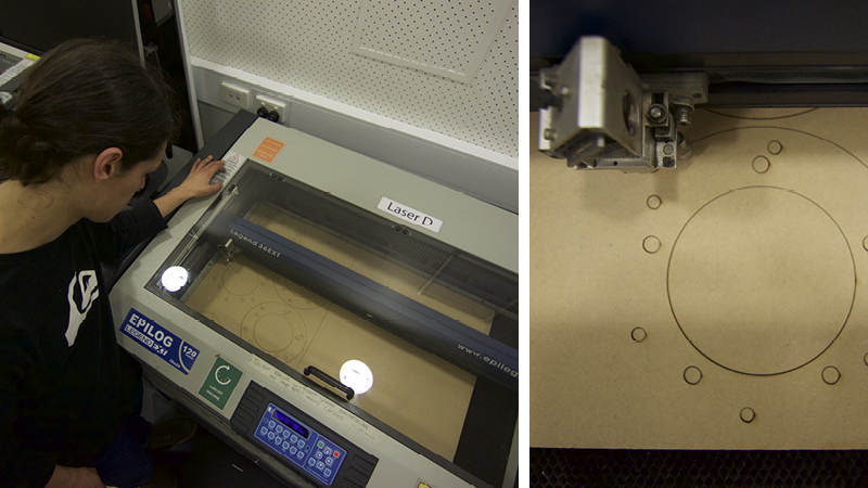
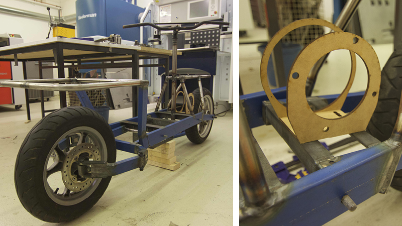
A sprocket adapter plate and a motor mount was needed. The easiest method was water jet cut steel plate, but the designs needed testing first. Laser cut MDF mock ups were the answer.
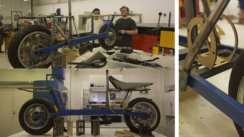
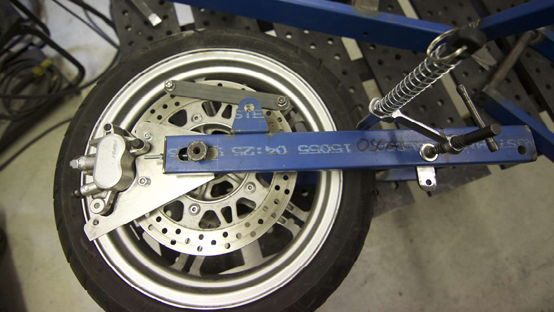
The wheels went on for the first time. Now able check that the motor mount will work.
Checking fitment of various components.
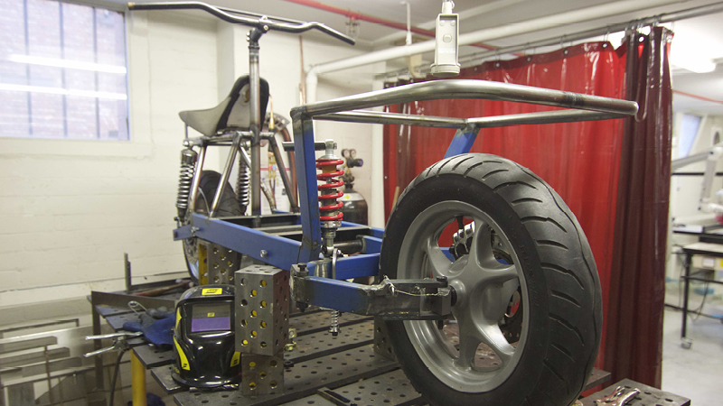
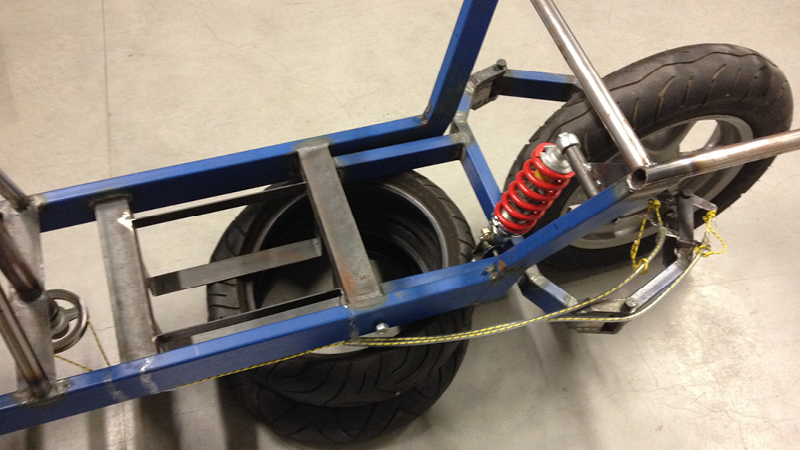
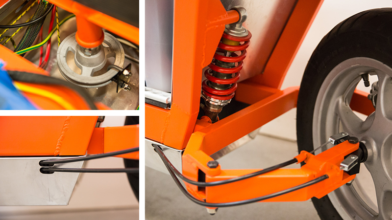
Suspension going in.
Single shock upfront from the rear of a Sach Madass. The two rear shocks are stock from an SR400 (Craig’s bike of choice).
Wiring headaches. The wiring is actually pretty simple, but it took a while to understand why certain things had to be done a certain way.
Creating an illustrative wiring diagram to ease the process.
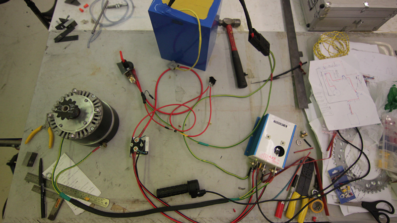
Successful bench test of the wiring.
Lot’s of welding jobs set up on the bench.
Motor mount and pulley clamp ready for welding.
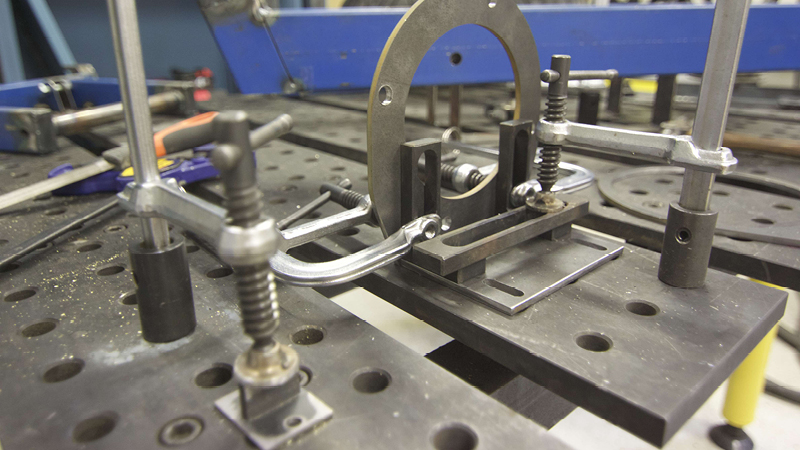
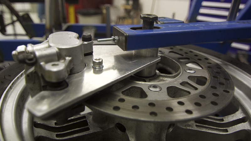
Rear brake mount assembly going together.
Aluminium axel spacer and brake caliper mount plate.
Rear claw nearly completed.
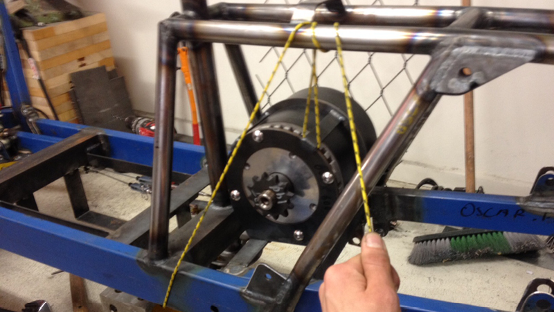
Using vinyl tubing and rope to measure the cable lengths/slack.
Welding motor mounts with your devil horns out \m/
Coreflute bodypanel test.
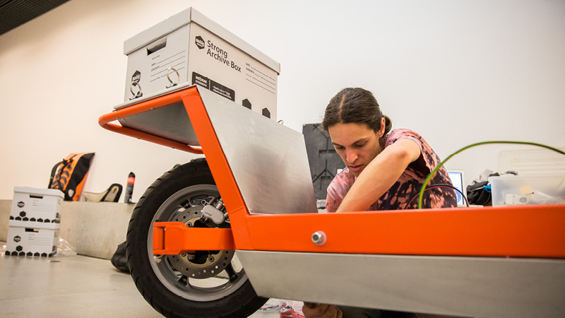
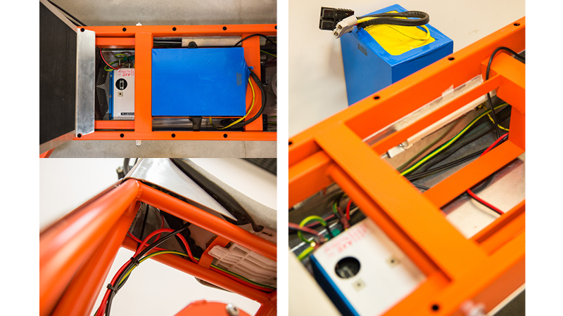
Component test fit: Making sure the controller, battery and solenoid don’t interfere with the steering cables and there’s space for wiring.
Welding the cable steering bracket: The one and only real stuff up of the project. Custom “clutch” cables were made for the pull-pull steering and the cable makers misinterpreted some dimensions (a fault of the drawings not being 100% explicit.) and they made them too short for the brackets I had in place. Simply meant making and welding a new bracket. This wasted valuable time, but lessons were learnt.
Mounting the motor.
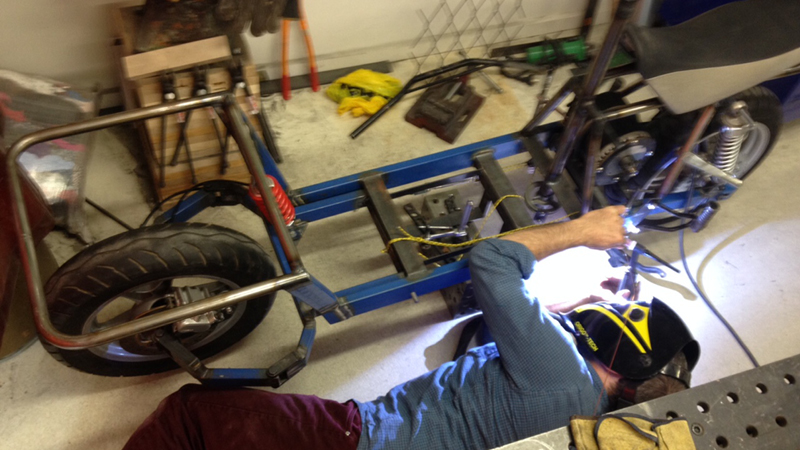
Welding centre stand brackets.
Centre stand in place.
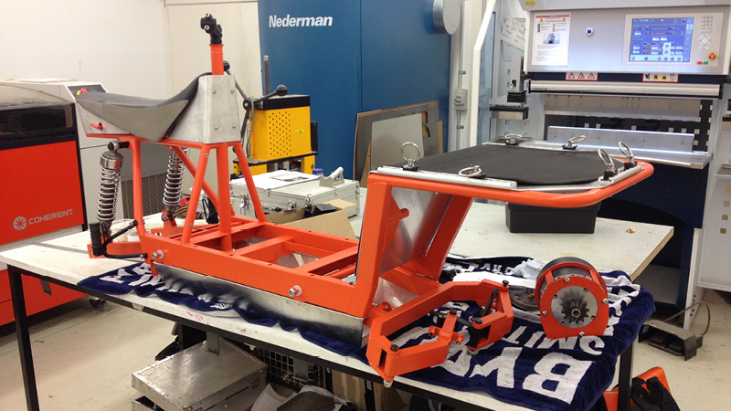
Taking a look at it outside.
The rear end.
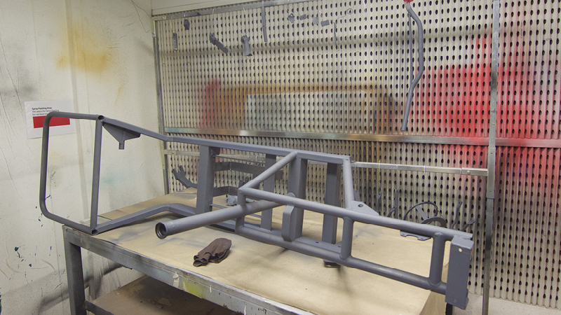
Priming the frame in the spray booth.
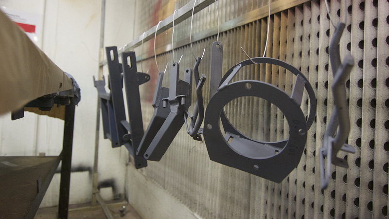
Primed parts.
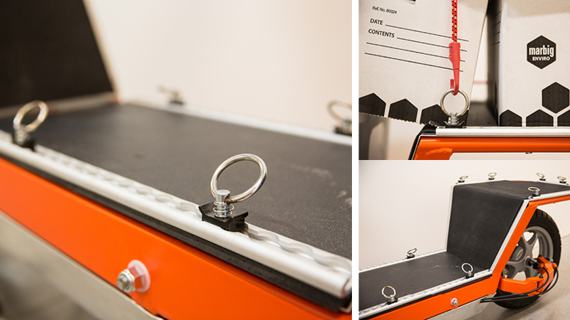
Cargo deck with aluminium cargo rails.
Aluminium bodywork coming together.
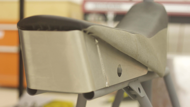
Tail section: You can see in this shot the rear suspension mounts. It’s two steel plates that sandwich a threaded rod connector that has been cut at the right angle.
Tail section 2: Kill switch keyhole.
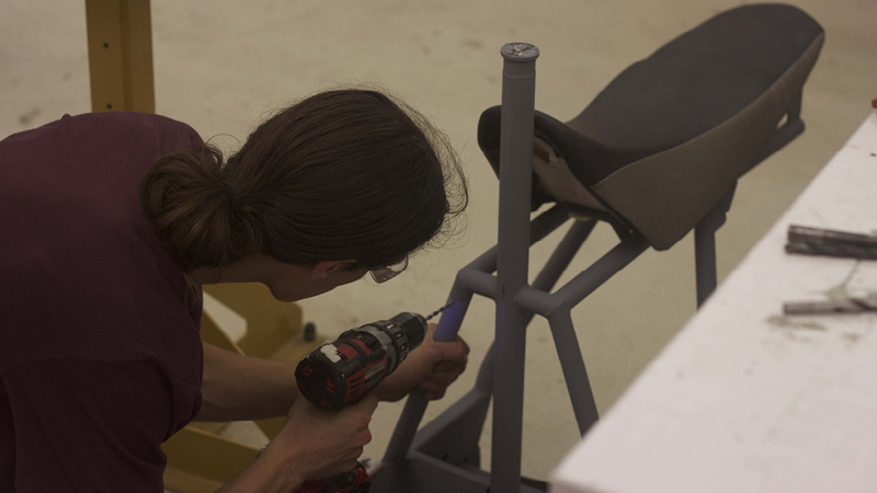
Drilling for nutserts: A lot of the bodypanels were bolted to nutserts in the frame.
Front rack: More cargo rails and laying up the rubber mat.
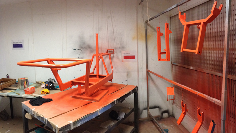
Orange: First coat done.
BRIGHT ORANGE: At this point there was a worry that it was too bright, but once the panels and components were on it would look less intimidating.
Headstock panel and kill switch.
Fitting panels.
Fitting panels 2.
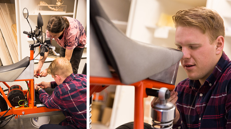
“Final” assembly. Friends were called into action for the final push to complete the bike.
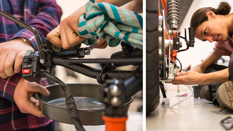
Bleeding brakes.
Fiddling with wiring.
More fiddling with wiring.
Fitting panels.
Loading up the battery.
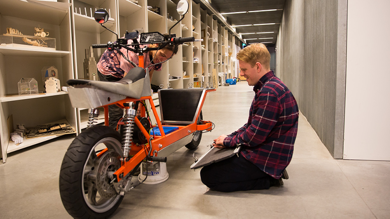
Maiden voyage down the hallway.
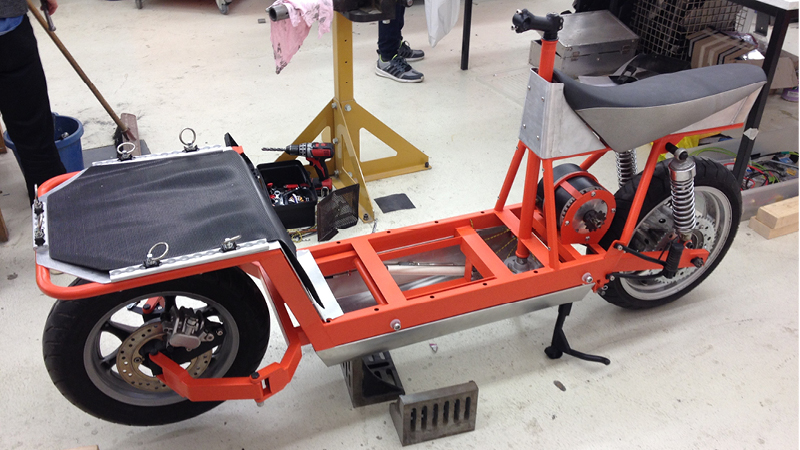
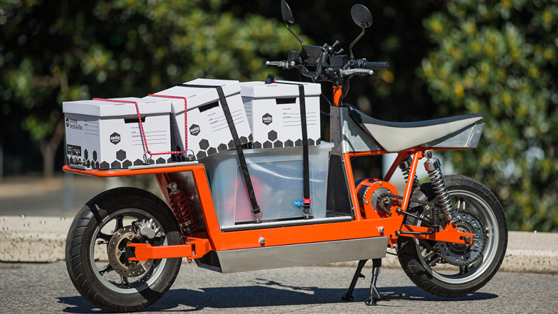
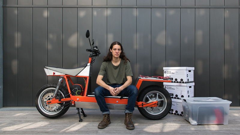
Finally together.
Cargo details.
Instrument/GPS details.
Front end movement.
Cable steering details.
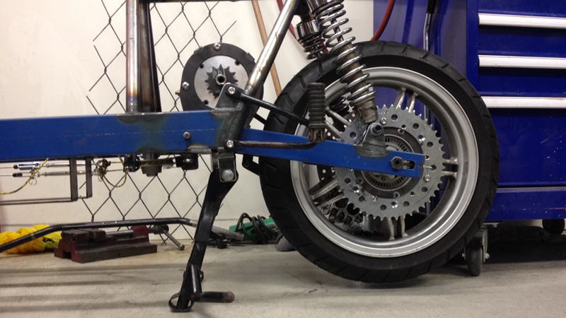
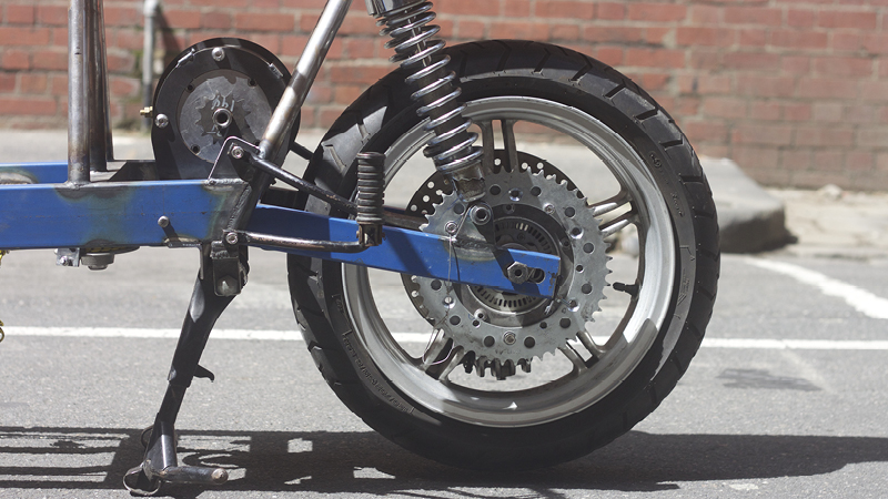
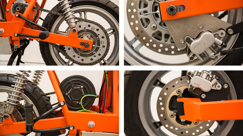
Drive train and brakes.
Electrics.
Killswitch.
A proud moment.
Take on any curb!
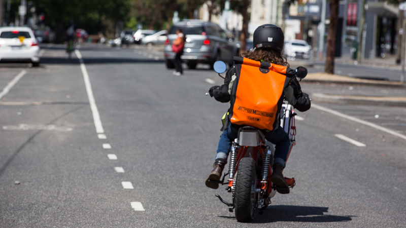
Off into the sunset.
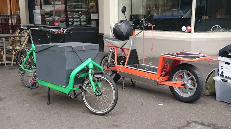
The cargo bicycles around Melbourne (especially the Bullitt bikes owned by Cargone Couriers) were a massive inspiration for the project. Here, the EsCargo is lined up next to Blane Muntz’s Bullitt bike. Blane helped out early on in the project by showing me around Melbourne in a day in his life as a cargo bicycle courier.
Steering adjustments in the home: Adjusting the cables is a frustrating job. Over time it has slowly been dialled in and the steering response has gotten a lot better. Still a lot of development needed.
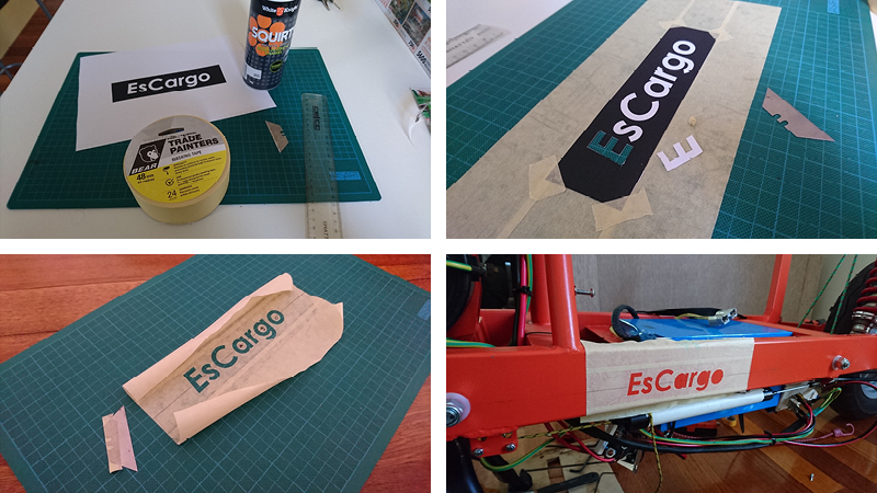
Making a stencil for the vehicle lettering.
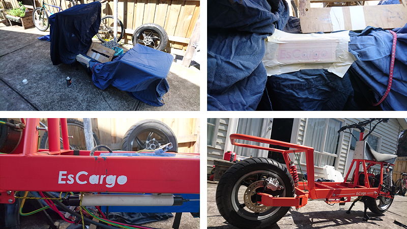
Stencilling lettering.
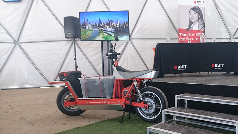
EsCargo was a finalist for a Green Innovation competition.
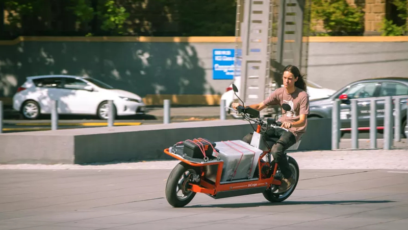
Showing the bike to GizMag: It’s quite fun once you learn the quirks! (photo: GizMag, Loz Blain)
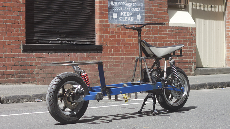
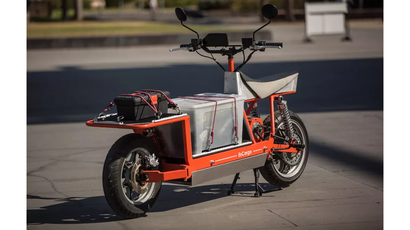
It’s current form: There are still many things to add, change, adjust and remake in order to really finish the prototype, but It’s an excellent starting point we’re very happy with. (photo: GizMag, Loz Blain)